Monday, June 25, 2007
Friday, April 13, 2007
Monday, February 5, 2007


Friday, December 22, 2006
Tuesday, December 5, 2006
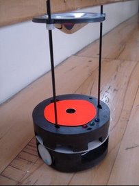
KOBOT videos, obstacle avoidance
For a detailed description of the obstacle avoidance algorithm please refer to Area measurement of large closed regions with a mobile robot, by Erol Sahin, Sertan Girgin and Emre Ugur.
Modifications performed in the software of short-range sensing system
In the previous post, we have given the code segment running in the host microcontroller which requests and then receives sensor reading from each 12F683. This code waits for the sensor reading to be sent indefinitely, which may hang up the host microcontroller. Watchdog timer of the host microcontroller is enabled to overcome this problem, which is actually quite successful. It is preferred to modify the code segment to prevent hang up, instead of using watchdog timer in 16F877A (watchdog timer is still used in 12F683's). The code is modified and is given below:
timeout = 0;
output_toggle(SENSOR0_TX);
while (!kbhit(SENSOR0)&&(++timeout<100))
...delay_us(1);
if(timeout<100)
...sensorData[0] = getc(SENSOR0);
else
...sensorData[0] = 0;
In this code, the host microcontroller waits for approximately 100 us for the sensor reading to be sent and if it is not received it sets the reading to 0 and passes to the next sensor. In this way, the host doesn't hang up indefinetly. Two important points to note in this code segment are:
- delay_us(1): The delay should be as small as possible not to miss the start bit.
- if(timeout<100): This if condition is used to test whether the program exited while condition due to timeout condition or reception of startbit. In this if statement, timeout condition should be checked instead of kbhit() because if the starbit is received, checking kbhit() will make 16F877A miss the next data bit (since kbhit() function will treat the next data bit as the start bit).
Deadlock in short-range sensing system
As explained in the previous posts, First sensor is working and An overview of the Short-range Sensing System, host microcontoller, sensor PIC, requests data from each 12F683 sequentially waiting to get data from each of them. When there is a problem with one of the 12F683's, sensor PIC gets into a deadlock. The following C-code (running on sensor PIC) explains the things more clearly:
output_toggle(SENSOR0_TX); //request pin is toggled to inform 12F683 to send sensor reading
while (!kbhit(SENSOR0)); //wait for serial data to be sent
sensorData[0] = getc(SENSOR0); //get serial data
When the request pin of 12F683 is toggled, an interrupt occurs and 12F683 immediately sends the current reading results to 16F877A, then it returns back to its measurements. The problem arises just at that point. There may be a chance that 12F683 be in a time critical section of the code and when it jumps to the interrupt vector, it looses time and may get stuck and stop working properly. When a certain 12F683 is in deadlock state 16F877A immediately fails since it waits the sensor sensor reading to be sent indefinetly. That seems to be exactly what we observe in the system.
In order to overcome this problem watchdog timer, defined by Wikipedia that: "A watchdog timer is a computer hardware timing device that triggers a system reset if the main program, due to some fault condition, such as a hang, neglects to regularly service the watchdog (writing a 'service pulse' to it, also referred to as 'patting the dog'). The intention is to bring the system back from the hung state into normal operation", feature of the PIC's is planned to be used.
Watchdog timers of both 16F877A and 12F683 micrcontrollers are enabled. It is easy to enable watchdog timer in CCS C compiler. The important point is to be careful in the delay loops, since microcontrollers wait in delay loops and watchdog timer can easily detect this as a deadlock and reset the microcontroller. To avoid that situation, the following is suggested in CCS C compiler:
/* Delay for 20 mhz crystal */
#use delay (clock=20000000, restart_WDT)
#use delay macro is used by the delay loops everytime they are called. When we add the term restart_WDT the watchdog timer is reseted when there is a delay loop which prevents watchdog timer to operate incorrectly. Selection of the period of watchdog timer is dependent on the application and the algorithm used as an example (this example is given for 16F877A microcontroller) we have used 288 ms as the period which means that when the microcontroller hangs for about 288 ms, watchdog timer will reset it.
setup_wdt(WDT_288MS);
After setting the watchdog timer both for 16F877A and 12F683 microcontrollers, we started the stress test and observed that the system operates as expected.
Yet another problem with short-range sensing system
The test is as follows:
- The host micrcontroller of the sensor card, 16F877A, takes readings from the eight sensors and sends them continuously to PC via its hardware serial port. In the original configuration it will send the reading information to the PIC in the main control card via I2C, but for the sake of simplicity and ease in debugging, we prefer to send data serially to PC instead.
- PIC in the main control card, continuously blink the blue debugging LED in front of the robot which is like an heart-beat signal to indicate that this PIC alive and working.
When the system is powered up it is observed that the system works perfectly almost all the time. But when the power is turned on then turned off it is observed that both the main PIC and the host PIC in the sensor card lock. They don't work properly, sensor PIC stops to send serial data and main PIC can't blink the blue LED.
Solution(1):
The first solution that comes to mind is the use of a big DC power supply. This power supply has big capacitors, may not satisfy the minimum initial rise time, which is stated as 0.05V/ms in the datasheet, requirement of the PIC's. A battery-pack having 3-AAA sized 2300mAh NiMH batteries is utilized in the tests and the power is rapidly turned on and turned off. The result is the same it is even worse, both of the PIC's lock almost everytime in the tests.
Solution(2):
The problem seems to be harder than we thought. We have catagorized the problem as power-up problem and search for a solution. Reset alternatives of PIC is analyzed thoroughly from the datasheet and from the perfect book about the PIC microcontrollers, Design with PIC Microcontrollers by John Peatman, http://www.amazon.com/Design-Pic-Microcontrollers-John-Peatman/dp/0137592590. There are several ways to solve power-up problems. These are:
- Power-up timer: Power-up timer together with oscillator start-up timer facilitates a delay of approximately 28ms before the code execution begins in PIC's. Because errorenous execution of the code may be observed if PIC starts to run code before its voltage is below 4V (4V is specific to our case, standard 16F877A microcontroller may work between 4-5V, LF type PIC's may work at much lower voltages but with a lower clock rate). The power-up timer has already been enabled in our case but couldn't solve our problem. The power-up timer has one draw-back it can't function properly when the minimum initial rise time criteria isn't satified.
- Brown-out detector: Brown-out is defined by Wikipedia that "the voltage level is below the normal minimum level specified for the system". The "A" series PIC's have built in brown-out detectors that can be enabled by the configuration bits. The brown-out detector as stated by Peatman has four important functions: (a) When the PIC is turned off and voltage drops below 4V, the minimum operating voltage, brown-out detector puts the PIC in reset condition, (b) when a brown-out condition occurs, i.e. when the system is power-up from a DC supply and the input voltage (220V DC, in Turkey) to the DC supply drops below a certain value DC supply can not regulate its output hence voltage may drop below 4V, in this case brown-out detector again puts PIC in reset condition until voltage stabilizes above 4V, (c) while the PIC is operating power glitch may occur, which causes VDD (supply voltage) to drop below 4V and brown-out detector puts PIC in reset state, if the glitch is longer than 100 us, until VDD stabilizes, (d) brown-out reset circuit puts PIC in reset state when the power-on reset conditions aren't satisfied, i.e. brown-out detector resets PIC even the minimum initial rise time is not achived (please note that there is no mechanism in PIC to prevent mulfuction when the initial minimum rise time criteria is not satisfied, dispite the brown-out detector).
Brown-out detectors of both main PIC (16F877A) and sensor PIC's (16F877A and 12F683's) are enabled and the previous power-up test is repeated. The power is again rapidly turned on and turned off, and the system works perfectly! Brown-out detector has solved our power-up problem.
Monday, December 4, 2006
Strange blue LED problem!

 Open-drain output diagram of RA4
When we look at the datasheet of 16F877A, we have noticed that the RA4, has open-drain output characteristics, as shown in the above figure. It is noted in http://www.brouhaha.com/~eric/pic/open_drain.html that:
Open-drain outputs are outputs which at any given time are either actively sinking current (i.e., low voltage, typically considered logic 0) or are high impedance, but which never source current (high voltage, logic 1). Open-drain refers to the drain terminal of a MOS FET transistor. The equivalent concept on a bipolar device is called open-collector.
Most microcontrollers don't have dedicated open-drain outputs. On some PICs the PA4 pin (also known as RTCC) may be used as an open-drain output. Most of the other port pins are bidirectional, and have separate output data registers and direction registers. On the PIC, the direction registers are called TRIS registers, an abbreviation for Tri-state, which is actually a trademark of National Semiconductor. The TRIS register bits should be set to logic 0 for lines that should be active outputs, and logic 1 for lines that should be high-impedance inputs. Note that this is the reverse of the conventions used by almost all other microcontrollers and peripheral devices.
In order to obtain the effect of open-drain output, it is necessary to use the TRIS register bit to control the output rather than the more usual use of the data output register. This is most easily accomplished by leaving the appropriate bit of the data output register set to 0, and setting the corresponding TRIS bit to 0 when the output should sink current, and 1 when the output should be in the open-drain (high-impedance) state.
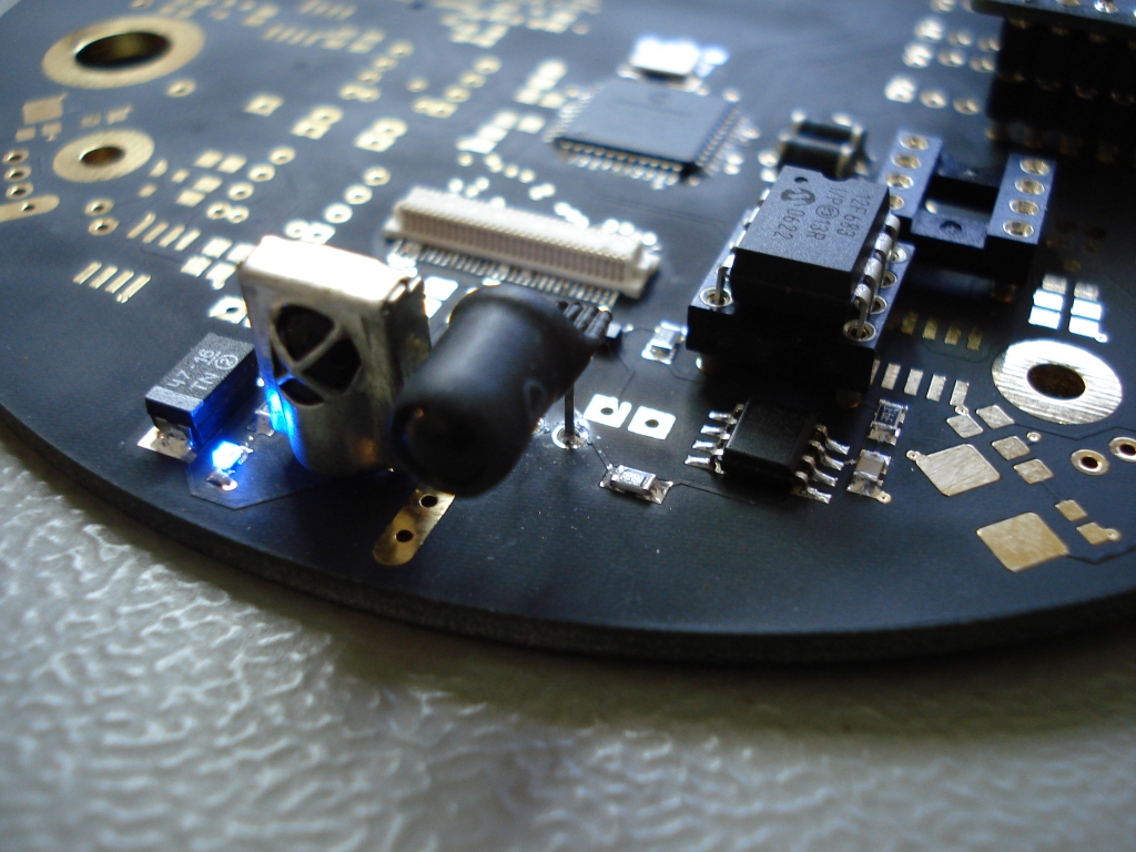
The important point to note is that open-drain ports can not source current, they can only sink current. In our configuration, shown in Blue LED-PIC connection diagram, we are sourcing current to the blue LED's to lit them. This connection type is appropriate for I/O pins having TTL characteristic only, not suitable for open-drain output pins. Hence a small modification is performed on the LED of sensor 5. The ground connection of the sensor is cut using a sharp knife and 5V is connected to this trace instead. The polarity of the LED is also reversed since current will flow from 5V to RA4 port of the PIC (the port will sink current).
The following C-code(CCS PIC C compiler) is used to turn on and turn off the LED:
To turn on LED:
output_low (SENSOR5_LED); //changes the state of RA4 to LOW
bit_clear(trisa,4); // makes RA4 as output and RA4 sinks current
To turn off LED:
output_low (SENSOR5_LED); //changes the state of RA4 to LOW
bit_set(trisa,4); // makes RA4 as input which means it is in high-impedance state and no current flows
Main control card


Currently, the microcontroller and SI9988's (without feedback circuit) are mounted.
Tests made so far:
- Programming via KOBOT data cable,
- Hardware serial connection at 115.2k,
- Debugging leds (mounted on the sensor board. red, green and blue),
- Buzzer(mounted on the sensor board, 12mm piezo),
- Motor driving test using 78Khz PWM signal.
Tests left:
- I2C communication with the sensor board microcontroller,
- Programming via XBee OEM RF module,
- I2C communication with the PXA card,
- Motor voltage feedback circuit control
First video from KOBOT:
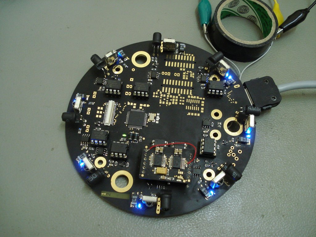
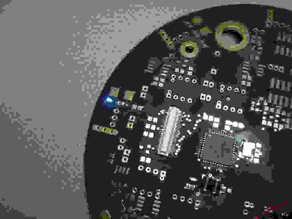
An overview of the Short-range Sensing System
The host microcontroller, which is a PIC 16F877A, requests the current reading results from each sensor, and waits for the data to be sent and continues this process until all of the sensors sent their reading results (the result can be a number from 1 to 8 according to range or 0 for no object condition.). The first thing that the host microcontroller does is to lit the corresponding blue LED nearby each sensor if the sensor has detected an object within its operating range. The LED's are controlled by the host microcontroller instead of 12F863's. This is a necessity rather than a decision since 12F683 is an 8-pin microcontroller, all of its pins are used for power, operation of IR LED/detector and serial communication and no pin is left for the indicator LED. This necessity is also useful for debugging the operation of the sensors and the communication between sensors and the host microcontroller since the LED's can only be lit when sensor is operating correctly and serial communication is successful.
The host microcontroller, after turning on/off the blue LED's according to the reading results, sends readings of eight sensors via I2C to the main microcontroller, which is again a PIC 16F877A, upon its request.
Monday, November 27, 2006
Saturday, November 25, 2006
Design Notes-2
First Sensor is working
Friday, November 24, 2006
Quick Notes-1
Thursday, November 23, 2006
Design Notes-1
- Flying capacitors on the bottom side of the power card: These components are very critical for output to be ripple free and very sensitive to heat. So, try to finish soldering as possible as quickly to avoid even slight differences in the capacitance values.
- TPS60130's: Do not forget to apply grease to the PowerPADs (two rectangles with 9 vias on each) before soldering. PowerPADs are needed to dissipate the heat on the ground plane.
- Input capacitors.
- Output capacitors, tantal and ceramic.
- Voltage divider for low battery input circuit: 680k, 390k and 100nF on the bottom side.
- Low battery indicator led and its resistor.
- Microcontroller and its peripherals.
- JST connector on the sensor board.
- Fuse on the sensor board
- Female header on the sensor board. You may have difficulty while soldering +5V and GND pins due to large power planes!
- Male precision headers. A simple trick: Plug them to the female headers on the sensor board and then plug the power card to the male headers. Solder four pins, unplug the power card and solder rest of them. With this way, alignment problems can be avoided.
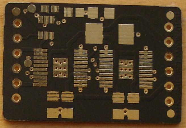
Soldering the Power Card
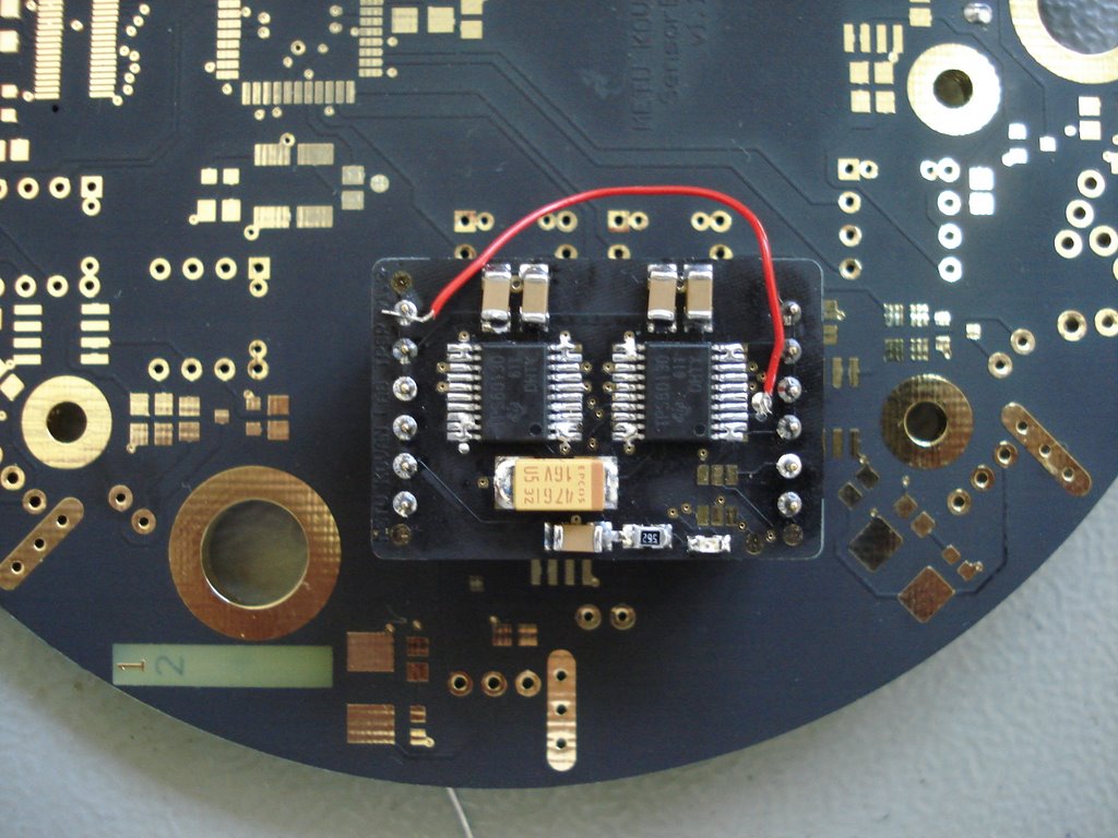
Power Card