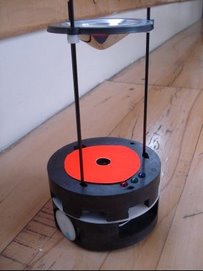
The test is as follows:
- The host micrcontroller of the sensor card, 16F877A, takes readings from the eight sensors and sends them continuously to PC via its hardware serial port. In the original configuration it will send the reading information to the PIC in the main control card via I2C, but for the sake of simplicity and ease in debugging, we prefer to send data serially to PC instead.
- PIC in the main control card, continuously blink the blue debugging LED in front of the robot which is like an heart-beat signal to indicate that this PIC alive and working.
When the system is powered up it is observed that the system works perfectly almost all the time. But when the power is turned on then turned off it is observed that both the main PIC and the host PIC in the sensor card lock. They don't work properly, sensor PIC stops to send serial data and main PIC can't blink the blue LED.
Solution(1):
The first solution that comes to mind is the use of a big DC power supply. This power supply has big capacitors, may not satisfy the minimum initial rise time, which is stated as 0.05V/ms in the datasheet, requirement of the PIC's. A battery-pack having 3-AAA sized 2300mAh NiMH batteries is utilized in the tests and the power is rapidly turned on and turned off. The result is the same it is even worse, both of the PIC's lock almost everytime in the tests.
Solution(2):
The problem seems to be harder than we thought. We have catagorized the problem as power-up problem and search for a solution. Reset alternatives of PIC is analyzed thoroughly from the datasheet and from the perfect book about the PIC microcontrollers, Design with PIC Microcontrollers by John Peatman, http://www.amazon.com/Design-Pic-Microcontrollers-John-Peatman/dp/0137592590. There are several ways to solve power-up problems. These are:
- Power-up timer: Power-up timer together with oscillator start-up timer facilitates a delay of approximately 28ms before the code execution begins in PIC's. Because errorenous execution of the code may be observed if PIC starts to run code before its voltage is below 4V (4V is specific to our case, standard 16F877A microcontroller may work between 4-5V, LF type PIC's may work at much lower voltages but with a lower clock rate). The power-up timer has already been enabled in our case but couldn't solve our problem. The power-up timer has one draw-back it can't function properly when the minimum initial rise time criteria isn't satified.
- Brown-out detector: Brown-out is defined by Wikipedia that "the voltage level is below the normal minimum level specified for the system". The "A" series PIC's have built in brown-out detectors that can be enabled by the configuration bits. The brown-out detector as stated by Peatman has four important functions: (a) When the PIC is turned off and voltage drops below 4V, the minimum operating voltage, brown-out detector puts the PIC in reset condition, (b) when a brown-out condition occurs, i.e. when the system is power-up from a DC supply and the input voltage (220V DC, in Turkey) to the DC supply drops below a certain value DC supply can not regulate its output hence voltage may drop below 4V, in this case brown-out detector again puts PIC in reset condition until voltage stabilizes above 4V, (c) while the PIC is operating power glitch may occur, which causes VDD (supply voltage) to drop below 4V and brown-out detector puts PIC in reset state, if the glitch is longer than 100 us, until VDD stabilizes, (d) brown-out reset circuit puts PIC in reset state when the power-on reset conditions aren't satisfied, i.e. brown-out detector resets PIC even the minimum initial rise time is not achived (please note that there is no mechanism in PIC to prevent mulfuction when the initial minimum rise time criteria is not satisfied, dispite the brown-out detector).
Brown-out detectors of both main PIC (16F877A) and sensor PIC's (16F877A and 12F683's) are enabled and the previous power-up test is repeated. The power is again rapidly turned on and turned off, and the system works perfectly! Brown-out detector has solved our power-up problem.

No comments:
Post a Comment