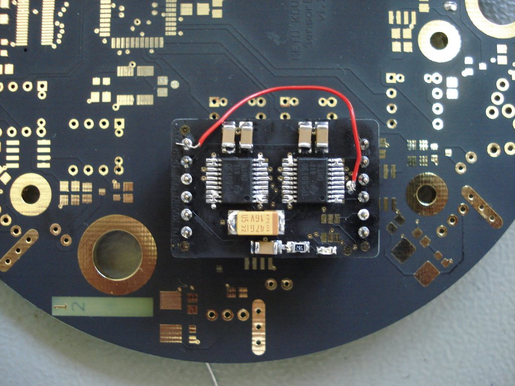
The power card is soldered and seen on top of the sensor board. The critical components in the card is the two TPS60130 step-up converters, the ceramic input capacitors, the ceramic output capacitors and the ceramic flying capacitors which are not seen on the picture since they are on the bottom side. There is also one SMD red LED (near the bottom right corner) to show the condition of the battery. The red cable is used to connect Vin to the ENABLE pin of TPS60130 which makes the power card always ON. This configuration is temporary and for testing purposes only. There will be a PIC 10F202 microcontroller that will take input from LOW BATTERY output of TPS60130 and from power button of the Kobot. In this way Kobot can be turned on and turned off by the user. Also when the battery is low, the microcontroller sends a signal to the microcontroller on the main card to take precautions before the system is shutdown. The power system includes also a fuse mounted on the bottom side of the sensor board.
No comments:
Post a Comment