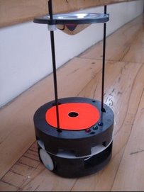

Main control card is used to execute the main behavior algorithm of the KOBOT. It is 20x80mm in size and has a PIC16F877A microcontroller at 20 MHz, two SI9988 motor driver IC's from Vishay, a PCA9306 from TI for I2C voltage level conversion between 3.3V and 5V systems and two MAX3371's from MAXIM for voltage level conversion between 3.3V XBee OEM RF module mounted on the sensor board and PIC16F877A. (XBee module has not been mounted yet and will be mounted and tested after I2C tests between main control card and sensor card microcontrollers.) The main control card is connected to sensor board via a 60-pin HIROSE connector. The microcontroller is programmed via ICSP (In Circuit Serial Programming via 5 pins) using the KOBOT data cable. A serial connection for this microcontroller is also available on the data cable connector. This connection is designed configurable as hardware serial or software implemented serial connection via 0R0s. Motor control IC's have also voltage or current feedback capability. In this card we have implemented the voltage feedback circuit.
Currently, the microcontroller and SI9988's (without feedback circuit) are mounted.
Tests made so far:
- Programming via KOBOT data cable,
- Hardware serial connection at 115.2k,
- Debugging leds (mounted on the sensor board. red, green and blue),
- Buzzer(mounted on the sensor board, 12mm piezo),
- Motor driving test using 78Khz PWM signal.
Tests left:
- I2C communication with the sensor board microcontroller,
- Programming via XBee OEM RF module,
- I2C communication with the PXA card,
- Motor voltage feedback circuit control
First video from KOBOT:

No comments:
Post a Comment