Monday, November 27, 2006
Saturday, November 25, 2006
Design Notes-2
Log for smd XTAL problem:
- At first ECX-53B 20MHz XTAL is mounted with two 22pF capacitors. The pic is programmed but does not work.
- Then ECX-53B unmounted and a normal dip XTAL is mounted while 22pF capacitors still mounted. The pic does not work again.
- The normal dip XTAL is unmounted and a programming test is performed without any XTAL successfully.
- 22pF capacitors are unmounted and the pic is tested using the normal dip XTAL and works.
- Then ECX-53B (previously unmounted one) is mounted again without 22pF capacitors and the pic works for about 3 minutes.
- A new ECX-53B is mounted without 22pF capacitors and the pic works (and still working with this XTAL). At this last step the inconsistency between ECX-53B's mentioned in "Quick Notes-1" post is realized.
First Sensor is working
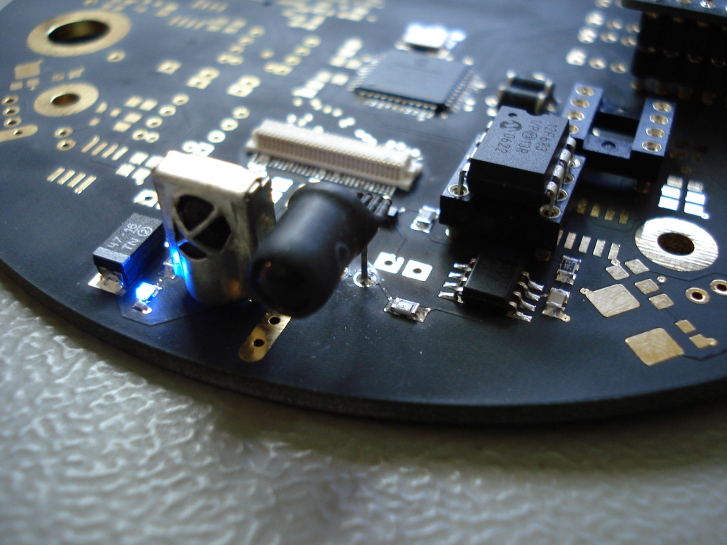
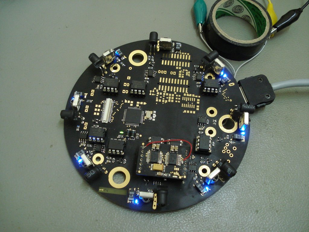
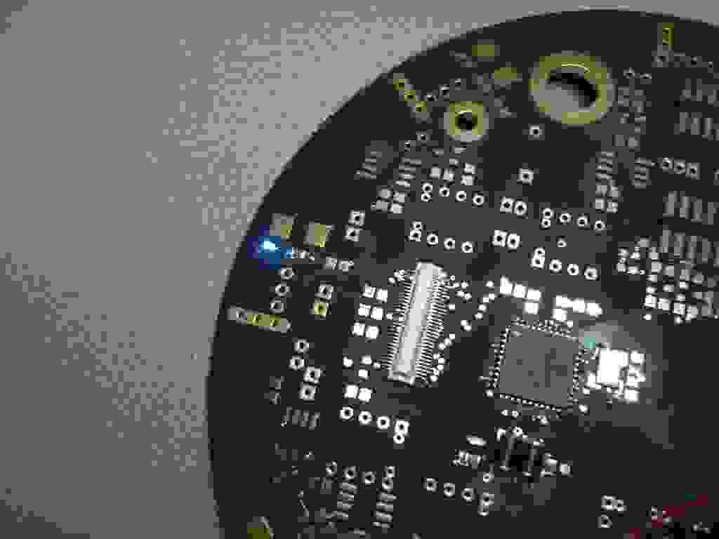
First sensor is mounted and working properly. But some calibration is needed. There is not any problem with the range (~30 cm using 12x12cm white paper) but 8th level is very narrow. Blue led is shining since the sensor senses an object. The sensor has a PIC12F683 microcontroller and measures the distance using IR signals. It sends distance information to the sensor card controller (PIC16F877A) upon the controller's request. Request is made using interrupt features. Blue led is controlled by the sensor card controller. Object information is also sent to the PC via serial connection at 115200 baud using the Kobot data cable for testing purposes.
Friday, November 24, 2006
Quick Notes-1
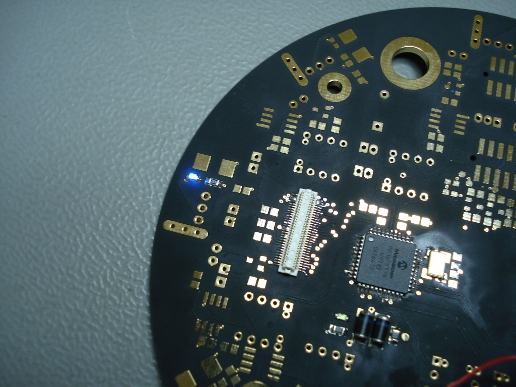
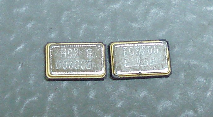
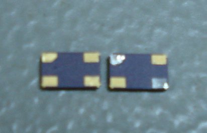
- PIC16F877A on the sensor board is mounted and first led test is OK! A problem occured with the 20MHz smd XTAL. It is solved by unmounting 22pF capacitors. Why they caused a problem is unknow yet! But we have realized that two different but same part numbered XTAL has different pin out style. The pictures clearly shows this inconsistency. :S
- A simple serial communication test is also performed successfully.
- Now it is time to move on first sensor....
Thursday, November 23, 2006
Design Notes-1
A possible soldering order for the components of the power system:
- Flying capacitors on the bottom side of the power card: These components are very critical for output to be ripple free and very sensitive to heat. So, try to finish soldering as possible as quickly to avoid even slight differences in the capacitance values.
- TPS60130's: Do not forget to apply grease to the PowerPADs (two rectangles with 9 vias on each) before soldering. PowerPADs are needed to dissipate the heat on the ground plane.
- Input capacitors.
- Output capacitors, tantal and ceramic.
- Voltage divider for low battery input circuit: 680k, 390k and 100nF on the bottom side.
- Low battery indicator led and its resistor.
- Microcontroller and its peripherals.
- JST connector on the sensor board.
- Fuse on the sensor board
- Female header on the sensor board. You may have difficulty while soldering +5V and GND pins due to large power planes!
- Male precision headers. A simple trick: Plug them to the female headers on the sensor board and then plug the power card to the male headers. Solder four pins, unplug the power card and solder rest of them. With this way, alignment problems can be avoided.
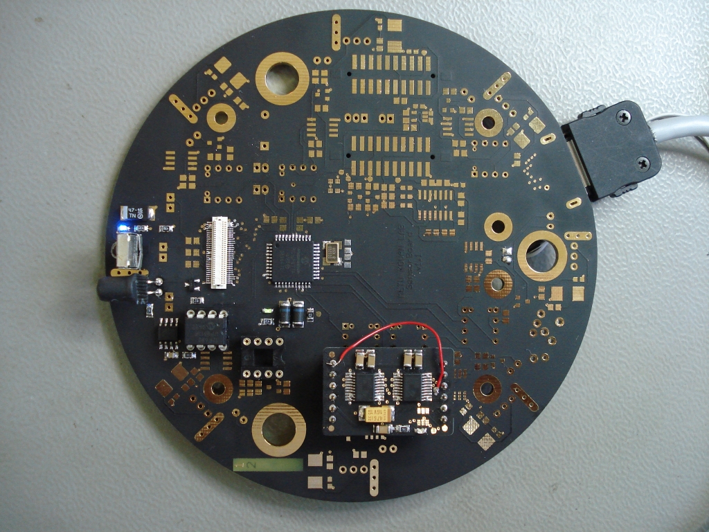
Soldering the Power Card
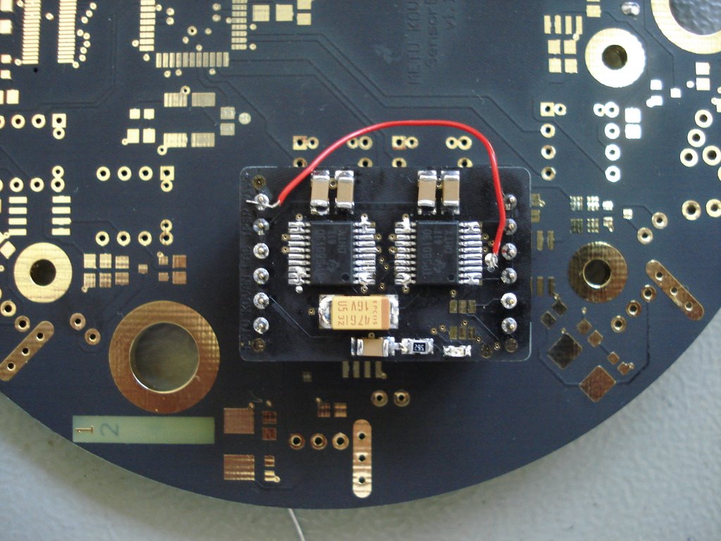
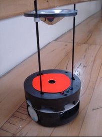
The power card is soldered and seen on top of the sensor board. The critical components in the card is the two TPS60130 step-up converters, the ceramic input capacitors, the ceramic output capacitors and the ceramic flying capacitors which are not seen on the picture since they are on the bottom side. There is also one SMD red LED (near the bottom right corner) to show the condition of the battery. The red cable is used to connect Vin to the ENABLE pin of TPS60130 which makes the power card always ON. This configuration is temporary and for testing purposes only. There will be a PIC 10F202 microcontroller that will take input from LOW BATTERY output of TPS60130 and from power button of the Kobot. In this way Kobot can be turned on and turned off by the user. Also when the battery is low, the microcontroller sends a signal to the microcontroller on the main card to take precautions before the system is shutdown. The power system includes also a fuse mounted on the bottom side of the sensor board.
Power Card
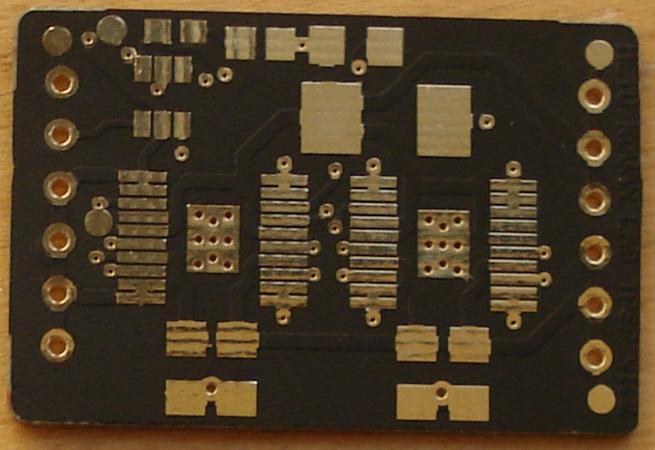
We started building the Kobot from the power card. The power card is the main power source of Kobot's. It is 30X20mm in size and has two TPS60130 step-up converter chips from TI. The input to the power card is either from one-cell Li-Poly battery having a nominal voltage of 3.7V or from 3-cell AAA-size NiMH batteries having a nominal voltage of 3.6V. The output is a constant, almost ripple free 5V.
Wednesday, November 22, 2006
Subscribe to:
Posts (Atom)