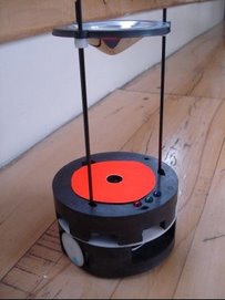
As explained in the previous posts, First sensor is working and An overview of the Short-range Sensing System, host microcontoller, sensor PIC, requests data from each 12F683 sequentially waiting to get data from each of them. When there is a problem with one of the 12F683's, sensor PIC gets into a deadlock. The following C-code (running on sensor PIC) explains the things more clearly:
output_toggle(SENSOR0_TX); //request pin is toggled to inform 12F683 to send sensor reading
while (!kbhit(SENSOR0)); //wait for serial data to be sent
sensorData[0] = getc(SENSOR0); //get serial data
When the request pin of 12F683 is toggled, an interrupt occurs and 12F683 immediately sends the current reading results to 16F877A, then it returns back to its measurements. The problem arises just at that point. There may be a chance that 12F683 be in a time critical section of the code and when it jumps to the interrupt vector, it looses time and may get stuck and stop working properly. When a certain 12F683 is in deadlock state 16F877A immediately fails since it waits the sensor sensor reading to be sent indefinetly. That seems to be exactly what we observe in the system.
In order to overcome this problem watchdog timer, defined by Wikipedia that: "A watchdog timer is a computer hardware timing device that triggers a system reset if the main program, due to some fault condition, such as a hang, neglects to regularly service the watchdog (writing a 'service pulse' to it, also referred to as 'patting the dog'). The intention is to bring the system back from the hung state into normal operation", feature of the PIC's is planned to be used.
Watchdog timers of both 16F877A and 12F683 micrcontrollers are enabled. It is easy to enable watchdog timer in CCS C compiler. The important point is to be careful in the delay loops, since microcontrollers wait in delay loops and watchdog timer can easily detect this as a deadlock and reset the microcontroller. To avoid that situation, the following is suggested in CCS C compiler:
/* Delay for 20 mhz crystal */
#use delay (clock=20000000, restart_WDT)
#use delay macro is used by the delay loops everytime they are called. When we add the term restart_WDT the watchdog timer is reseted when there is a delay loop which prevents watchdog timer to operate incorrectly. Selection of the period of watchdog timer is dependent on the application and the algorithm used as an example (this example is given for 16F877A microcontroller) we have used 288 ms as the period which means that when the microcontroller hangs for about 288 ms, watchdog timer will reset it.
setup_wdt(WDT_288MS);
After setting the watchdog timer both for 16F877A and 12F683 microcontrollers, we started the stress test and observed that the system operates as expected.